Accelerate Time-to-Market with Optimal
Lighting Designs
TracePro provides luminaire designers with an industry-leading design environment that combines accuracy and comprehensive functionality. Luminaire design typically requires precise adherence to system performance criteria, such as spatial and angular light distribution, uniformity, intensity, and spectral characteristics, in addition to aesthetic considerations like appearance when lit and unlit. With TracePro, designers can trust that the simulated performance and aesthetics will align with the final product, minimizing the need for expensive prototype iterations.
Streamlined Mechanical Design for Luminaires
Intuitive CAD Interface and Model Import
Mechanical Design for luminaires can be efficiently achieved using TracePro’s interactive solid modeling tools, which feature a familiar, intuitive CAD interface. Designers can also import models from widely-used CAD programs, including SolidWorks, ProE, and AutoCAD.
Seamless Integration with RayViz™ for SolidWorks
RayViz™ for SolidWorks allows seamless integration of optical and mechanical properties within the same CAD file, enabling parallel design workflows between TracePro and SolidWorks.
Accurate Representation of Light Sources and Surface Properties
Versatile Source Modeling Options
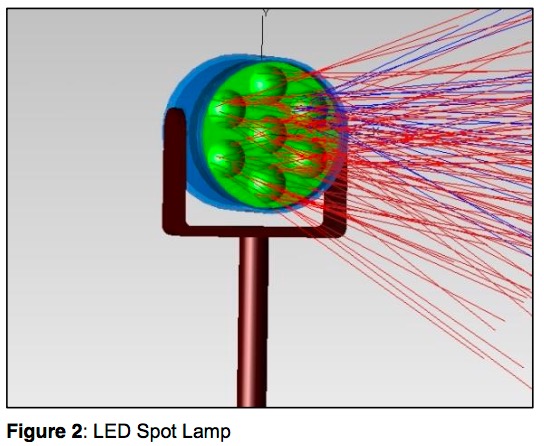
Light Sources and Surface Properties in TracePro are modeled using grid, surface, or ray file sources derived from measurement data. You can also specify sources using actual geometry and fully define them using TracePro’s sketching capabilities.
Extensive Properties Database
TracePro’s properties database includes source and material data for a wide range of commercially available lamps, LEDs, optical components, plastics, metals, and epoxies.
Lens and Reflector Design Optimization
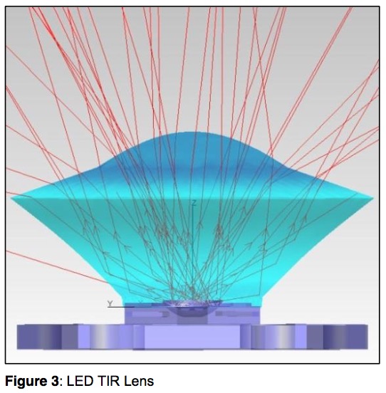
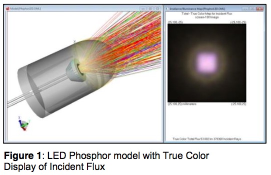
Lens and Reflector Design capabilities allow users to optimize lenses, reflectors, and light sources based on performance criteria and industry standards. Analyze the efficiency of individual components and complete systems to evaluate illuminance and candela distributions, ensuring optimal light performance.
Advanced Design Optimization Features
Design Optimization begins by sketching the initial luminaire layout using TracePro’s sketch utility. Once the optimization variables are defined, graphical variable limits are displayed for visual confirmation throughout the optimization process. This helps prevent overlapping control points, reducing the risk of creating non manufacturable designs.
TracePro’s Interactive Optimizer is a highly intuitive tool easily mastered by any optical design engineer. The main functions of the tools include:
-
Surface List
Includes available surface types used to draw the objects, such as Planar, BSpline (free, X, Y, XY), Parametrized (biconic surface), 2D profile (asymmetric, symmetric, elliptical), and user-defined Path (2D, 3D). -
Object View
Creates objects from the surface list using Radial Symmetry, Extrusion, Lens, Sweep, and Biaxial methods; establishes initial parameters that can be adjusted in the Property Editor. -
Property Editor
Varies depending on the selection, but generally includes origin, tilt center and angle (X, Y, Z), tilt then shift, thickness, material type, surface properties, draft angle, and refractive index -
Optimization
Uses operands to specify values on which to optimize, including: flux, color space (CIE), irradiance distribution, irradiance profile, intensity, candela profile, and uniformity; allows you to define your own optimization targets.