TracePro Optimization
Interactively Refine Your Design to Achieve Optimal Performance
Optimization for Streamlining the Prototyping Process
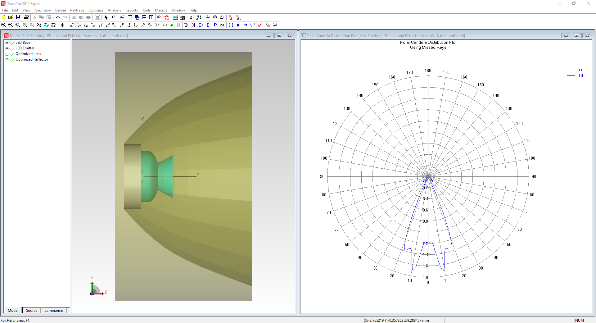
TracePro streamlines the prototype-to-manufacturing process for optical and illumination systems using its interactive optimizer. Different from traditional optimizers, TracePro offers an easy-to-use and unique capability to interactively monitor and control the process every step of the way.
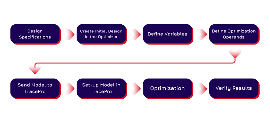
Beginning the Design Process
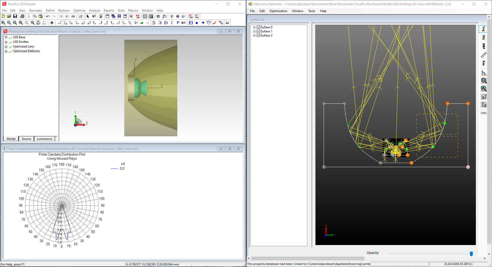
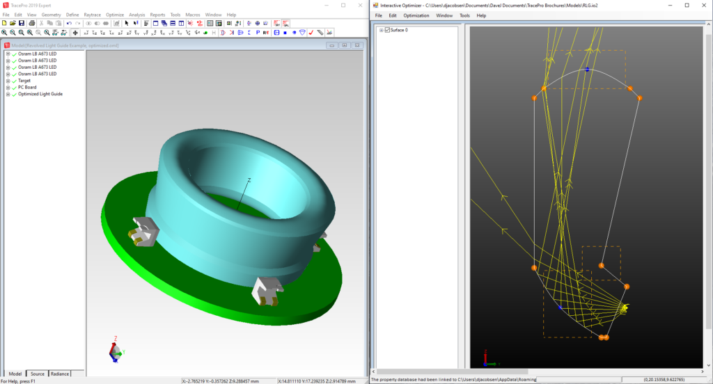
You start the design process by sketching the starting design, digitizing variable limits directly into the CAD sketch utility and establishing a merit function using intensity, efficiency, irradiance, radiance/luminance, color, and/or uniformity parameters. You can trace rays, then drag control points to interactively see the effect on your design as the rays update in real time.
The merit function uses weights to balance the multiple operands based on your desired targets.
Macro Language Capabilities
You can use TracePro’s powerful macro language to control interaction with the created geometry, modify optical properties for each surface and solid object, and control positioning of solid objects. Each variable can be visually checked before, during, and after optimization.
Optimization Methods
The TracePro optimizer uses the downhill simplex method, also known as the Nelder-Mead method, for optimization.
The downhill simplex method is a local optimizer that converges to the local minimum solution closest to the starting point. During an optimization, you have complete control of the process and can monitor the interim solutions. You can stop the optimizer and change the initial starting parameters, then re-start the optimization. This allows you to control the process and test for better solutions in less time.
TracePro’s Interactive Optimizer is a highly intuitive tool easily mastered by any optical or design engineer.
The main functions of the tool include:
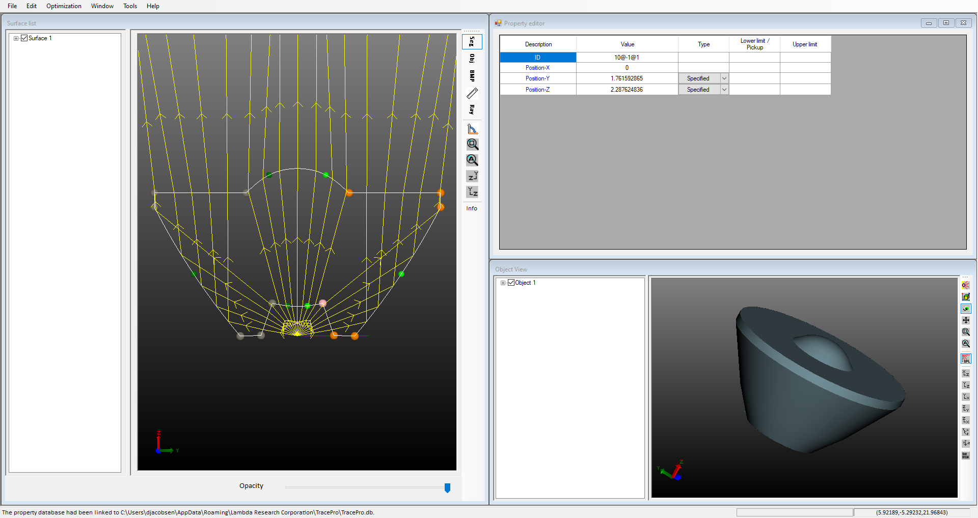
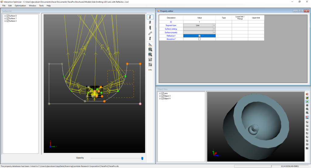
- Surface List
The Surface List encompasses a variety of surface types essential for creating objects. These include planar surfaces, b-spline surfaces (free, X, Y, XY), parameterized surfaces like biconic, freeform surfaces, 2D profiles (asymmetric, symmetric, elliptical), user-defined paths (both 2D and 3D), and reflectors. Each surface type serves a specific purpose in the design process, offering flexibility and precision in modeling complex optical systems.
- Object View
The Object View details the types of objects that can be created, such as lenses, extruded shapes, radially symmetric objects, sweeps, biaxial forms, reflectors, TIR lenses, freeform lenses, and advanced sweeps. This view establishes initial parameters for these objects, which can be adjusted in the Property Editor. The variety of object types allows for detailed and specific modeling of optical components.
- Property Editor
The Property Editor adjusts based on the selected object, generally including settings for origin, tilt center and angle (X, Y, Z), tilt then shift, thickness, material type, surface properties, draft angle, and refractive index. Additionally, users can define sliders for interactive property adjustments, enabling real-time manipulation and fine-tuning of optical elements to meet specific design requirements.
- Optimization Operands
Optimization Operands use multiple values for optimization, including flux, color space (CIE u’v’, CIE xy), irradiance distribution, irradiance profile, intensity, candela profile, uniformity, beam width, spot size, luminance, and photorealistic rendering. Users can also define custom operands or write Scheme macro programs to tailor the optimization process precisely to their needs, enhancing the design’s performance and efficiency.
- Optimization Variables
Nearly any design parameter can be designated as an optimization variable, offering extensive flexibility in refining the design. These variables can be set as relative or absolute, allowing designers to optimize specific aspects of their optical systems comprehensively. This capability ensures that every parameter can be adjusted for peak performance, providing a high level of control over the final design outcome.