RIFLSCOP.LEN - A 3.75X RIFLE SCOPE
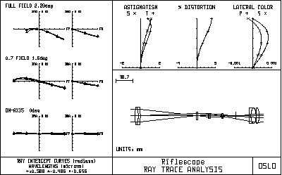
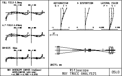
Riflscop shows the use of the pickup-length-minus (pkp lnm) command to hold a constant image location. Because this is commonly required in zoom systems, this command is often called a zoom solve. A rifle scope is an inverting telescope designed to be mounted on a rifle and used as a telescopic sight. The scope consists of four parts: an objective, an erecting system, a reticle, and an eyepiece. In use, the objective and erecting system for an image of an object at or near infinity on the reticle (or vice versa). The erector system in a real system contains tilt and decentering adjustments that provide alignment capability as well as compensation for windage and bullet drop, but the design included here does not include such adjustments. The overall system is afocal, and must be designed with generous eye relief to prevent injury when the rifle is fired. In fact, this system is one position of a zoom system. Surface 11, the last surface of the second erector doublet, is specified by a the command pk lnm 4 11 90.7025 command, sometimes called a zoom pickup, because it holds the total distance between surface 4 and 12 at 90.7025mm, no matter what value is given to any intervening thicknesses. The system is zoomed by changing thicknesses 5 and 8. To design the system, you can choose some value of th[8], then optimize the image quality by varying th[5]. This will produce the proper location (or locations - there may be two) of components and the magnification. By repeating this procedure for several values of th[8], you can construct a cam curve that shows how the elements must track to change the magnification. The lenses themselves can be designed with the system set at some particular magnification, or possibly at two different magnifications, to see how the optimum changes vs. magnification. Finally, you select one or the other (or some compromise) and make a final cam curve to complete the design. It is not necessary to use actual zoom optimization for a simple system such as this. The ray analyses shown on the next page show the performance of the scope at its normal magnification (3.75X), and also at a higher power (9.5X), which is achieved by changing th[5] to 15.208348, th[8] to 1.596579, the entrance beam radius to 18, and the field angle to .9 degrees. Note that the system has the afocal general operating condition set, so the ray displacements automatically are shown in radians. Ray displacements in afocal mode are actually direction tangents, not angles in radians, but are ordinarily so small that there is negligible difference.


