Lens Mirror and Reflecting Prism - Right-Angle Prism Entry
- Start from the doublet that you just entered. Change the lens identifier to "Right-angle prism/mirror example", then save the lens with the name prismirr.len. You will want to open the lasrdblt.len file later for optimization, so saving the current system with a different name will preserve the earlier system.
- Before entering any surface data, click Update >> Operating conditions >> Lens drawings, and modify the spreadsheet so that it looks like the following. The items to be changed are Image space rays and Number of field points for ray fans. These changes will make the Autodraw window more useful.

- Close the Lens drawing operating conditions spreadsheet and return to the surface data spreadsheet. Drag the bottom of the window frame down until there is room for four more rows, then move the cursor to the row button for surface 5. Now press SHIFT+SPACE four times to insert the additional rows (this is a shortcut to using the mouse), or click row button 5 and click the Insert Before toolbar icon 4 times. Remove the axial ray solve on surface 4 by typing 5 into the thickness SmartCell.
- Next you will insert the prism. Enter SF15 for the glass on surface 5. Click on the Special button for surface 6, select Surface Control >> General, and turn on TIR only. This means that rays will be reflected if they undergo total internal reflection and will fail otherwise. Note that for a TIR surface, the refractive index of the surface is the one for the medium into which the ray goes if it fails the TIR condition. The program knows that if t is totally internally reflected, the refractive index is the same as that in the incident medium.
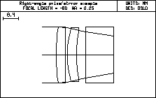
- Set the apertures of surfaces 5 - 7 to 15. Set the thickness of surface 5 to 15. The Autodraw window should now look as follows:

- Surface 6 will be the reflecting face of the prism, tilted at 45 degrees. Click the Special button and select the Coordinates item on the pop-up list. In the spreadsheet, enter 45 for TLA, and change the Tilt and bend button to Yes.
- Enter -15 for the thickness of surface 6. Thicknesses are negative after an odd number of reflections, as discussed previously. Enter 15*sqrt(2) for the aperture. (Note that It is possible to use standard math functions such as sqrt(2) in numeric input fields.)
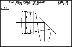
- The center of the turning mirror is to be 10mm below the prism. Set th 7 to -10. At this point, the Autodraw window and spreadsheet should appear as follows.


- Click Show >> Surface Data, then select All special data from the options list. The following should appear in the Text window.
*TILT/DECENTER DATA 6 DT 1 DCX — DCY — DCZ —
BEN TLA 45.000000 TLB — TLC — *SURFACE TAG DATA 6 TIR 1 The next step will be to add a turning mirror that reflects the beam so that it continues from left to right.
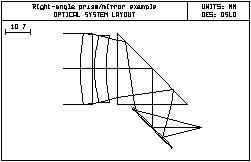
- Enter data for the turning mirror as shown below. Use an axial ray height solve to locate the final image surface, in the same manner as the laser doublet example. The mirror is entered using the Reflect (Hatch) item on the Glass Options list. This has no optical significance, but causes the back side of the mirror to be hatched on the drawing, as shown. Set the aperture to 12mm. Select Special, Coordinates to set the tilt to -45 degrees, and set the bend flag. After you have entered all the data, click the Toolbar Save icon (F3) to save the lens.


*TILT/DECENTER DATA 6 DT 1 DCX — DCY — DCZ — BEN TLA 45.000000 TLB — TLC
— 8 DT 1 DCX — DCY — DCZ — BEN TLA -45.000000 TLB — TLC —
*SURFACE TAG DATA 6 TIR 1
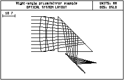
Note that an axial ray height solve is used on surface 8, even though the system has tilted elements. In the case where only tilts of plane surfaces are used, and the bend flag is used to propagate the optical axis, paraxial optics remains valid. It is interesting to investigate the TIR condition vs. the refractive index of the prism. For this purpose, use Update >> Operating Conditions >> Lens Drawings to set the number of default rays traced to 11. Then change the glass used for the prism to one with a lower index, say BK7. Note that several rays in the lower aperture now fail because they are not totally internally reflected.

