DOUBLET/MENISCUS SOLUTION
In this tutorial we will show a combination of a doublet and meniscus singlet for a high-speed (i.e., large N.A.) focusing systems. We will use a combination of MG01LAO126 followed by a meniscus singlet MG01LAM126, which will have approximately the desired paraxial properties and warrants evaluation.
- Click on File >> New. Enter the file name lasrcom2 and select catalog lens.
- Since the exact part number is known, click on the part name cell and type MG01LAO126, then press ENTER. This part appears in the window as shown. Click the green check mark to accept the insertion, close the database, and go to the surface data spreadsheet. On the surface data spreadsheet name the lens "Laser communication system".
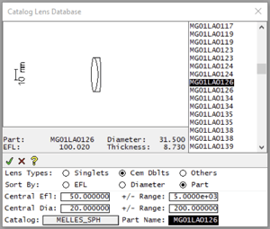
- Next, we will insert the meniscus singlet MG01LAM126 behind the doublet. First set the thickness of surface 3, which was entered with an axial ray height solve automatically by the program, to 1.0 by typing the number into the thickness field. Then, left click on the row button for surface 4 (it may be marked IMS) to select the row, then right click on the same row and execute Edit >> Insert Catalog Lens. When the catalog database window appears, enter the part number MG01LAM126, click the green check mark to accept the insertion, close the database, and go to the surface data spreadsheet. Next, select the wavelengths button in the surface data spreadsheet. Delete all wavelengths except for the first wavelength and set the first (primary) wavelength to 0.6328 micrometers (Helium-neon). Set the entrance beam radius to 15 (it will be mm by default) and turn on the Autodraw window. Add a solve to surface 5 by clicking on the thickness option button and selecting solves, axial ray height (value = 0). Left-click on the options button for surface 6 (now the IMS surface) and select the Autofocus – minimum RMS spot size with the option of On-axis (monochromatic) to find the best axial RMS spot focus. The surface data spreadsheet should be
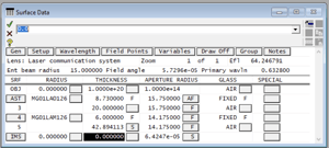
and the Autodraw window is
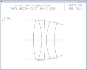
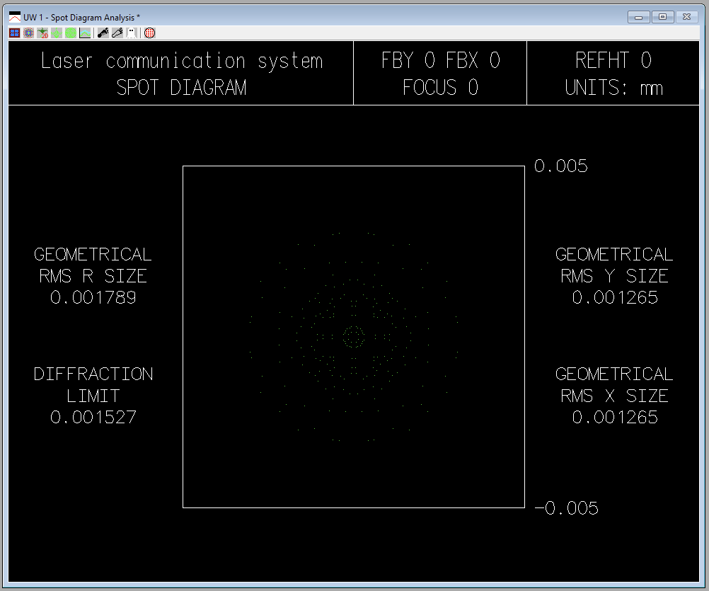
4. To analyze this system, select Evaluate >> Spot Diagram >> Single Spot Diagram… and left-click the O K button to accept the defaults . The geometric al RMS spot size is 0.001790 mm with a diffraction limit of 0.001527 mm. Whenever the geometric spot size approaches or falls below the diffraction - limit, diffraction effects become more important. In such case s , the geometrical spot diagram becomes a poor model for the physical lens performance. The Doublet/Meniscus spot size evaluation (with an inverted graphics background) is
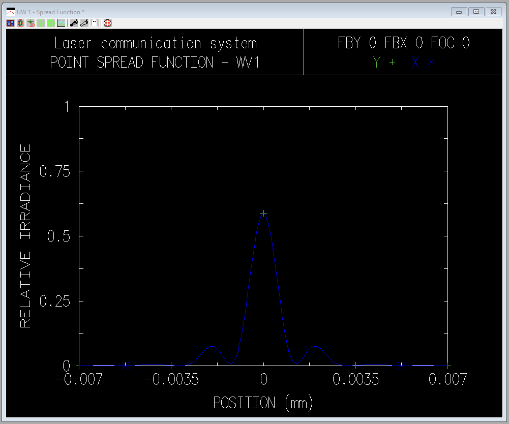
5. Since diffraction is important in this case, we will investigate the point-spread function for the axial point. Cl ick Evaluate >> Spread Function >> Plot PSF Scans… and left-click the OK button to accept the default options . The result is shown in the figure below (with an inverted background) . The first zero of the point-spread function appears at about +/- 0.0013 mm , in reasonable agreement with the geometrical analysis. If you want to change the scale on the plot right-click and select "Re-calculate with new parameters" to investigate how you can change the plot scale. For example, change the "Size of patch on image surface" to 0.005 to see how it scales the abscissa.
6. We have not attempted to optimize the spacing for this wavelength, so a better spacing solution likely exists. To study the spacing, we will set up an interactive design window to determine a better solution. First, set surface 3 thickness to 20 mm (direct), and set th 6 (it may say IMS) to 0.0, as shown in the following surface data spreadsheet
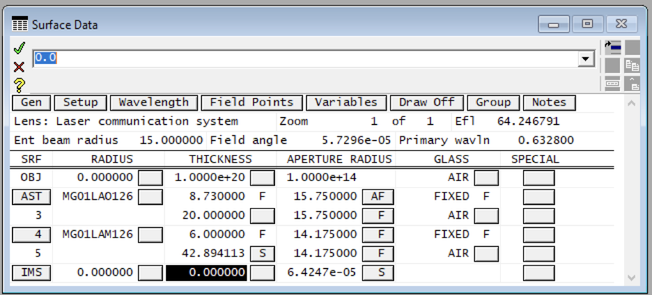
7. Click the green check mark to accept the changes and close the spreadsheet . Next, execute Optimize >> Slider-Wheel Design . Set the values in the spreadsheet to be the same as those shown below.
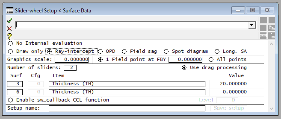
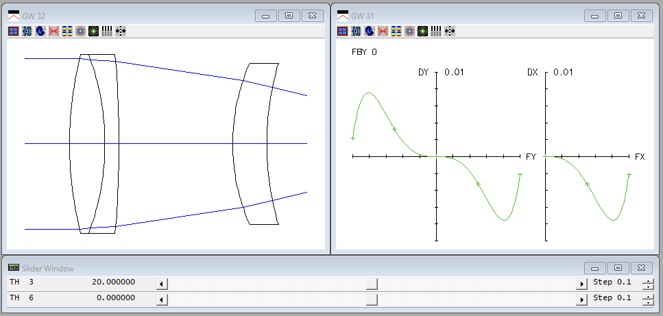
8. Once the data is set up in the slider-wheel set up spreadsheet, click on the green check mark to accept the changes and close it. You see two graphic windows, plus a slider window, as follows.
The ray-intercept curves show the displacement of rays from the reference point (here, the optical axis) as a function of the fractional aperture coordinate (FY 1 corresponds to the edge of the exit pupil). Horizontal lines along the axis correspond to a perfect optical system. Tilting corresponds to a focus shift, and curvature to aberrations. Ray-intercept curves are widely used in optical design because they provide a great deal of information with minimum computational effort. By dragging the th 3 slider back and forth after setting the step to 1, we can see that a better solution exists by setting the spacing to about 16 mm. The focus can be adjusted with the th 6 slider for further correction. To check the spot diagram corresponding to any lens configuration, double-click on the graphics window containing the spot diagram. Slider-wheel design is a great way to interactively see how a system varies with different parameter changes.

