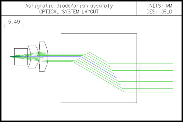
Diodassy is an example of combining two other systems to collimate the beam from an astigmatic diode laser. OSLO can accommodate astigmatic sources directly, without the need for an ancillary system that provides an approximate model. The example shows the use of spot diagrams and point-spread-function calculations. This file combines a diode-laser collimator (diodcoll.len), a cylindrical lens, and an anamorphic prism assembly (anaprism.len) to create an overall system that converts the light from a hypothetical diode laser having a beam divergence ratio of 3:1 and 10 microns of astigmatism into a collimated circular Gaussian beam having a wavefront quality of better than 0.25l. The diode is assumed to be single mode, and to have a numerical aperture in the xz plane of 0.3, and a numerical aperture in the yz plane of 0.1. The general layout of the system is as shown below. See diodcoll.len for additional information on the collimator and anaprism.len for additional information on the prism assembly.
*LENS DATA Astigmatic diode/prism assembly
| SRF | RADIUS | THICKNESS | APERTURE RADIUS | GLASS | SPE | NOTE |
| 0 | -- | 1.578414 | 1.0000e-06 | AIR | ||
| 1 | ELEMENT GRP | 10.200000 | 2.500000 A | SF11 | C * | |
| 6 | Collimator | 3.000000 | 4.500000 | AIR | Collimator | |
| 7 | ELEMENT | 1.000000 | 4.000000 | BK7 | C * | |
| 8 | Astig corr | -- | 4.000000 | AIR | * | Astig corr |
| 9 | ELEMENT GRP | 17.745114 | 4.000000 | AIR | * | |
| 14 | Prism assy | -- | 4.000000 | AIR | * | Prism assy |
| 15 | ELEMENT | 1.000000 | 4.000000 | BK7 | C * | |
| 16 | Out window | -- | 4.000000 | AIR | Out window | |
| 17 | -- | -- | 2.515146 S |
The astigmatism of the source is listed as the general operating condition sasd on the general operating conditions, as shown below. The value is the distance between the apparent source locations in the yz and xz meridians, 0.01 millimeters in the present example.
*OPERATING CONDITIONS: GENERAL
| Source astigmatic dist: | 0.010000 | Ray aiming mode: | Aplanatic |
| Temperature: | 20.000000 | Pressure: | 1.000000 |
The numerical aperture of the system is listed as 0.3 on the surface data spreadsheet. This tacitly assumes that the beam is circular. The ellipticity of the beam is indicated in the spot diagram operating conditions, since that is the place where it is important.
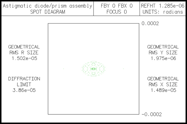
The spot size in the y-direction is called ssy, and the spot size in the xdirection is called ssx. Since the diode aperture is specified in NA, the spot size must be given as ss = th[0]*tan(asin(NA)). Which yields ssy = .159, ssx = .496. The data below show the results of a spot diagram. Note that since the system is afocal, the spot data appears in angular measure (radians). Note also that the spot is much larger in the x direction than the y direction, as confirmed by the plot.
*SPOT DIAGRAM: MONOCHROMATIC APODIZED APDIV 11.050000 WAVELENGTH 1 WAV WEIGHTS: WW1 1.000000 GAU SSY SSX 0.100000 0.300000 NUMBER OF RAYS TRACED: WV1 96 PER CENT WEIGHTED RAY TRANSMISSION: 6.532767 *SPOT SIZES RAY TRANSMISSION:
| GEO RMS YA | GEO RMS XA | GEO RMS RA | DIFFR LIMIT | CENTYA | CENTXA |
| 1.3927e-06 | 9.4077e-06 | 9.5102e-06 | 6.8377e-05 | -- | -- |
*WAVEFRONT RS WAVELENGTH 1
| PKVAL OPD | RMS OPD | STREHL RATIO | RSY | RSX | RSZ |
| 0.031658 | 0.007022 | 0.998711 | 1.1417e-10 | -- | -- |
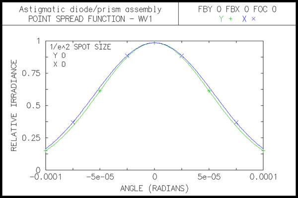
Spot diagrams only show the intersection points of rays with the image surface, not the ray weights. In the present case, the different ssx and ssy values put different weights on the rays (you can confirm this using the Calculate >> Display spot diagram command and selecting ray weights). The weights affect calculations such as energy distributions, and more particularly Fourier transforms, which are used to compute the intensity distribution in the emergent beam. The plot below shows the point spread function (i.e. the far-field intensity distribution) for the present system. The abscissa is in radians, since the evaluation is in afocal mode.