Beam TLC: ANAPRISM.LEN - A Beam Circularizer for Diode Lasers
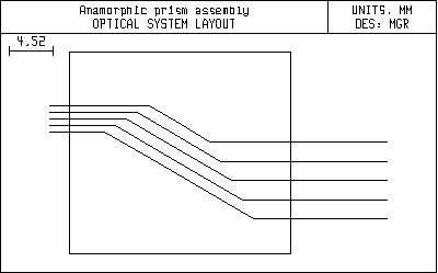
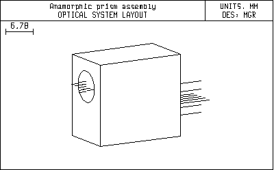
Anaprism shows the use of tilted and decentered surfaces, prisms, and the 3-dimensional drawing routines that allow OSLO to draw a pictures of any solid objects that can be specified as a series of vertices and faces.The optical system itself is sometimes used to convert an elliptical diode laser beam to a circular shape. Most diode lasers emit asymmetric beams. The numerical aperture is different in the yz and xz planes, and often the beam has astigmatism, which is a separate issue. One way to make the beam circular is to use a pair of anamorphic prisms, as shown in this example. The prisms used here are available as Melles Griot part number 06GPU001. They work in collimated light (otherwise they would add astigmatism), so in an actual application the prisms must be used in combination with a collimator. Such a system is included as the file diodassy.len, described below. The prisms have a vertex angle of 29.43333 degrees, a width of 12mm, and a maximum thickness perpendicular to the back face of 8.5mm. For a given entry angle to the first prism, the angle of the second prism is fixed by the requirement that the beam emerge parallel to itself. The displacement of the beam depends on the prism separation. The listing below shows how the system should be set up in OSLO. Surfaces 4 and 6 are expressed in the coordinate system of surface 1 using a return_coordinates ( rco) command. The rco command goes on the preceding surface and indicates that the coordinates of the next surface are to be taken according to the dcx, dcy, dcz, tla, tlb, and tlc relative to a base surface (here, surface 1). In order to prevent a confusing drawing caused by the tilted surfaces, the surfaces themselves are marked not drawable (in the Surface Control spreadsheet). A plan view of the system shows just the ray trajectories. Note that although the drawing makes it look like there are only two surfaces, there are actually 4. The rays are close enough to normal incidence on the other two that the drawing doesn't show them.
*TILT/DECENTER DATA
*SURFACE TAG DATA
*BOUNDARY DRAWING DATA SRF 1:


| SRF | RADIUS | THICKNESS | APERTURE RADIUS | GLASS | SPE | NOTE |
| 0 | -- | 1.0000e+20 | 1.0000e+18 | AIR | * | |
| 1 | -- | 6.000000 | 4.000000 AS | AIR | * | |
| 2 | -- | 5.872557 | 1.0000e-06 | SF11 C | * | |
| 3 | -- | -- | 1.0000e-06 | AIR | * | |
| 4 | -- | 5.872557 | 1.0000e-06 | SF11 C | * | |
| 5 | -- | -- | 1.0000e-06 | AIR | * | |
| 6 | -- | -- | 4.000000 | AIR | * | Prism assy |
| 7 | -- | -0.003198 | 4.179133 S |
| 2 | DT | 1 | DCX | -- | DCY | -- | DCZ | -- |
| TLA | -59.800000 | TLB | -- | TLC | -- | |||
| 3 | RCO | 1 | ||||||
| DT | 1 | DCX | -- | DCY | -- | DCZ | -- | |
| TLA | 29.433333 | TLB | -- | TLC | -- | |||
| 4 | DT | 1 | DCX | -- | DCY | -6.400000 | DCZ | 16.866459 |
| TLA | 29.292833 | TLB | -- | TLC | -- | |||
| 5 | RCO | 1 | ||||||
| DT | 1 | DCX | -- | DCY | -- | DCZ | -- | |
| TLA | -29.433333 | TLB | -- | TLC | -- | |||
| 6 | DT | 1 | DCX | -- | DCY | -6.400000 | DCZ | 23.000000 |
| TLA | -- | TLB | -- | TLC | -- |
| 1 | LMO | EGR | (6 surfaces) |
| 1 | DRW | AP | |
| 6 | DRW | AP |
| VX NBR | X | Y | Z | COORD SURF |
| 1 | 7.000000 | 7.000000 | -- | 1 |
| 2 | -7.000000 | 7.000000 | -- | 1 |
| 3 | -7.000000 | -14.000000 | -- | 1 |
| 4 | 7.000000 | -14.000000 | -- | 1 |
| 5 | 7.000000 | 7.000000 | 23.000000 | 1 |
| 6 | -7.000000 | 7.000000 | 23.000000 | 1 |
| 7 | -7.000000 | -14.000000 | 23.000000 | 1 |
| 8 | 7.000000 | -14.000000 | 23.000000 | 1 |
| PF NBR | VX1 | VX2 | VX3 | VX4 |
| 1 | 1 | 2 | 3 | 4 |
| 2 | 1 | 5 | 6 | 2 |
| 3 | 5 | 8 | 7 | 6 |
| 4 | 8 | 7 | 3 | 4 |
| 5 | 1 | 4 | 8 | 5 |
| 6 | 2 | 3 | 7 | 6 |
