Overcome LED Component Modeling Challenges to Achieve Optimal Results
TracePro is award-winning opto-mechanical software used for design, analysis, and optimization of optical and illumination systems. With its intuitive CAD interface and powerful features like interactive optimizers, TracePro offers a sophisticated and powerful optical design environment combined with a short learning curve to
reduce product time-to-market.
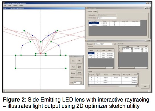
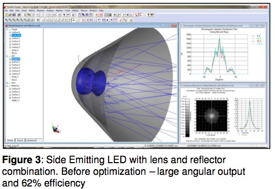
TracePro offers several methods to accurately model LED light sources and predict output performance. Sources can be modeled as grid sources, surface sources, image files, or extended sources using ray files derived from measurements. Sources can also be modeled by actual source geometry and defined completely using the TracePro sketch facility. Four surface design concepts are supported to address LED-specific design issues – imaging lenses, TIR lenses, hybrid imaging-and-TIR lenses, and reflectors.
Optical component design for LED systems presents unique challenges, each overcome with TracePro’s powerful utilities and feature sets. LED designers must address:
Smaller and more powerful light sources :
The focusing elements need to follow the same trend and become smaller in size while delivering the required system performance, e.g. a specific light intensity distribution profile.
Etendue requirements :
Narrow-angle LED emission is needed in many display applications. Optical components are needed to transform Lambertian emission into a narrow-angle distribution.
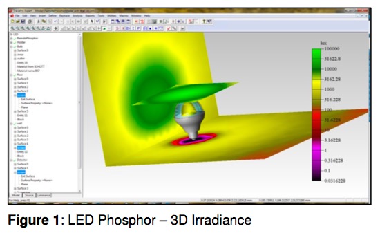
Color variation :
Needs to be controlled due to LED phosphor shapes and die size limitations.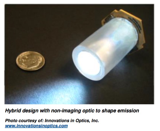
TracePro is a highly intuitive tool for simulating the properties and geometries of LED modules in order to determine output performance. The Surface Source Property Generator enables you to enter angular and spectral emission data quickly and accurately.
The Surface Source Property Generator enables you to digitize screen-captured spectral and angular radiation distributions from the LED manufacturer's data sheets, including: relative spectral power distribution and either polar
or rectangular radiation pattern distributions.
For applications in which near-field interaction is important, users can create an opto-mechanical model of the LED module by importing the geometry from mechanical CAD files available from the LED manufacturers, or by directly creating the geometry in TracePro based on manufacturers’ specifications.
You can model the complete packaged LED – cup, lens, die, etc. – and then apply material, surface, and fluorescence properties using the Apply Properties dialog box.