TOLERANCING
- To run a tolerance analysis on the lens, use a copy of the lens, not the original file. Change all the variables back to direct specification except the thickness of the image surface, which will be used as a compensator during tolerancing.
- Click Options >> Update Tolerance Data to open the tolerance data spreadsheet. The only tolerance of present interest is the second thickness. The ISO 10110 default value for this thickness is 0.2 mm, which is much too loose for the present system. Change the tolerance to 0.05 mm, and close the spreadsheet.

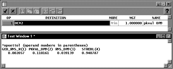
- Click Options >> User-Defined Tolerancing >> Setup operands. The *opsettol star command will be executed, and the operands spreadsheet will open. For the tolerance operand, enter ocm2, and enter the name pkval opd, as shown.

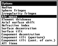
- To compute the effect of a .05 mm tolerance on the peak-to-valley opd, click Options >> User-Defined Tolerancing >> Sensitivity. An options list will pop up, as shown below. Select Air space, and click OK. After a short time, the text window should contain an analysis similar to the following.

*TOLERANCE SENSITIVITY ANALYSIS MERIT FUNCTION FOR NOMINAL SYSTEM: 0.110161 AIR SPACE TOLERANCE MERIT FUNCTION CHANGE COMPENSATED CHANGE SRF TOLERANCE PLUS PERT MINUS PERT PLUS PERT MINUS PERT 2 0.05 1.284532 1.292483 0.308596 0.284308
STATISTICAL SUMMARY UNCOMPENSATED COMPENSATED WORST CASE CHANGE 1.292483 0.308596 STANDARD DEVIATION RSS 1.292483 0.308596 UNIFORM 0.746216 0.178168 GAUSSIAN 0.568451 0.135724
COMPENSATOR STATISTICS COMP MEAN STD DEV MAX TH 5 0.000183 0.029274 0.029457
- The analysis shows the effects of a .05 tolerance on the merit function, which represents the peak-to-valley opd. You may be interested in the tolerance that can be allowed to produce a given change, say .15, which would bring the system
to (approximately) the diffraction limit. Click Options >> User-Defined Tolerancing >> Inverse Sensitivity. Select Air Space, then enter .15 in response to the prompt for allowed change. The text window will then show that
the allowed tolerance is about 16 microns if the focus is not adjusted, or 34 microns if the focus is used to compensate for a spacing error.
*INVERSE SENSITIVITY ANALYSIS MERIT FUNCTION FOR NOMINAL SYSTEM: 0.110161 ALLOWED CHANGE IN ERROR FUNCTION: 0.150000 AIR SPACE TOLERANCE ALLOWED TOLERANCE SRF UNCOMPENSATED COMPENSATED 2 0.016983 0.034557
