
A PCB-to-panel indicator array can look simple in CAD and still fail at the panel. One channel may appear brighter than the next. Different LED colors may not look balanced at the same drive condition. Light from an active channel may reach an adjacent indicator that should be dark. By the time those problems appear in molded hardware, the available fixes may involve the LED drive, the light-pipe geometry, the PCB, the panel, or the tooling.
Consider a hypothetical design review for a dense network-equipment indicator panel. The assembly uses separate LED dies and a molded light-pipe array, but the optical requirements have not been defined. The review team has no specified viewing position, no channel-matching limit, and no off-to-on crosstalk limit. This is not a documented Lambda Research customer case. It is a representative scenario that shows why the optical test must be defined before the geometry is frozen.
This guide focuses on rigid light pipes that carry light from PCB-mounted LEDs to individual panel indicators. It does not replace the existing guidance on uniform illumination and extraction features or the general TracePro light-pipe optimization workflow. The subject here is narrower: how to specify, model, and compare brightness matching and crosstalk in an indicator array.
Define brightness and crosstalk before changing the geometry
A useful simulation starts with the acceptance test. The target luminance for an indicator depends on its size, color, viewing distance, viewing angle, ambient illumination, panel contrast, and the applicable human-factors requirements. There is no universal luminance target for every product. Define the measurement geometry and operating condition, then set the target with the team responsible for the product specification.
Brightness matching also needs an explicit definition. One practical metric for channels intended to look equal is the ratio of the highest measured channel luminance to the lowest under the same stated conditions:
matching ratio = highest channel luminance / lowest channel luminance
A value of one would mean equal measured luminance. The acceptable departure from one belongs in the product specification. For indicators of different colors, use the appropriate photometric result and the specified LED spectra and drive conditions. Equal radiant flux does not imply equal perceived brightness.
Crosstalk can be expressed as the luminance of an adjacent indicator that should be off divided by the luminance of the driven indicator:
crosstalk ratio = adjacent off-channel luminance / driven-channel luminance
Measure both values from the same eye position, viewing angle, ambient condition, and model state. Trace one LED source at a time when diagnosing channel-to-channel leakage. The acceptable ratio must come from the product requirement or a representative visual evaluation. Generic pass or fail percentages are not defensible across different products.
Model the LED and its placement tolerance
The source definition controls every result downstream. Model each LED die as a separate source at its actual position, including separate dies in bicolor or RGB packages. Use manufacturer data or measured source data where available. TracePro supports grid, surface, and file light sources. A TracePro text ray file records ray start position, direction, and flux at minimum. Confirm the file's origin, normalization, wavelength treatment, and operating condition before using it as evidence for a production decision.
When a validated ray file is not available, build a qualified approximation from the emitting aperture and the manufacturer's angular data. Record that approximation as a source of uncertainty. A model that reproduces a datasheet curve is not automatically correlated to the specific LED, drive current, temperature, or package tolerance in the assembly.
Sweep the mechanical variables that can change coupling: the LED-to-pipe gap, lateral offset, angular offset, entrance size, entrance shape, and pipe position relative to the panel. Compare the reported flux at selected entrance and output surfaces for each case. Avoid using a generic percentage for gap loss or entrance-shape improvement. Those results depend on the source, aperture, spacing, and angular distribution in the actual model.
Separate the main crosstalk paths
An adjacent indicator can receive unwanted light through several parts of the assembly. Treat each as a hypothesis to test rather than assuming the light stays inside the clear pipe.
Sidewall leakage is one path. Rays can leave a pipe at a bend, taper, textured surface, support contact, or other location where the total internal reflection condition is not retained. Some of that light may enter a neighboring pipe. Candidate changes include the bend geometry, spacing, surface treatment, or an opaque barrier, but the model should show which change reduces flux at the off channel.
A common clear runner or joined base is another possible path. It can provide an optical connection between channels. Compare the current geometry with separated clear features, an interrupted bridge, or an opaque frame. Do not assume an opaque feature solves the problem until its material properties and placement are represented.
The PCB can also carry stray light. Light that misses the entrance may reflect from the solder mask, nearby packages, or other board features before entering a neighboring pipe. Use measured or supplier-supported reflectance data for the modeled board finish. Candidate mitigations include a closer entrance, a local absorbing region, or a mechanical shield.
The panel is a fourth path. A translucent panel, a thin wall, or a scattering feature can spread light laterally between indicator openings. Model the panel with characterized optical data. A visual guess at color or opacity is not a bulk-scatter measurement.
TracePro's Incident Ray Table provides tabular results for rays incident on a selected surface. Its Path Sorting Table provides a sortable view of sampled paths incident on a selected surface and supports filtering and interactive ray viewing. Use those tools to inspect the paths reaching an off-channel surface. A Flux Report provides incident, absorbed, and lost flux information for selected model elements. Together, these outputs help separate the path carrying unwanted light from the symptom visible at the panel.
Calculate brightness matching from a fixed viewing setup
TracePro supports luminance and radiance maps for multiple eye positions. Place the eye positions and viewing angles required by the product specification, then keep them fixed across design cases. Extract one channel value using the same region and statistic for every indicator. Do not compare the peak of one channel with the average of another.
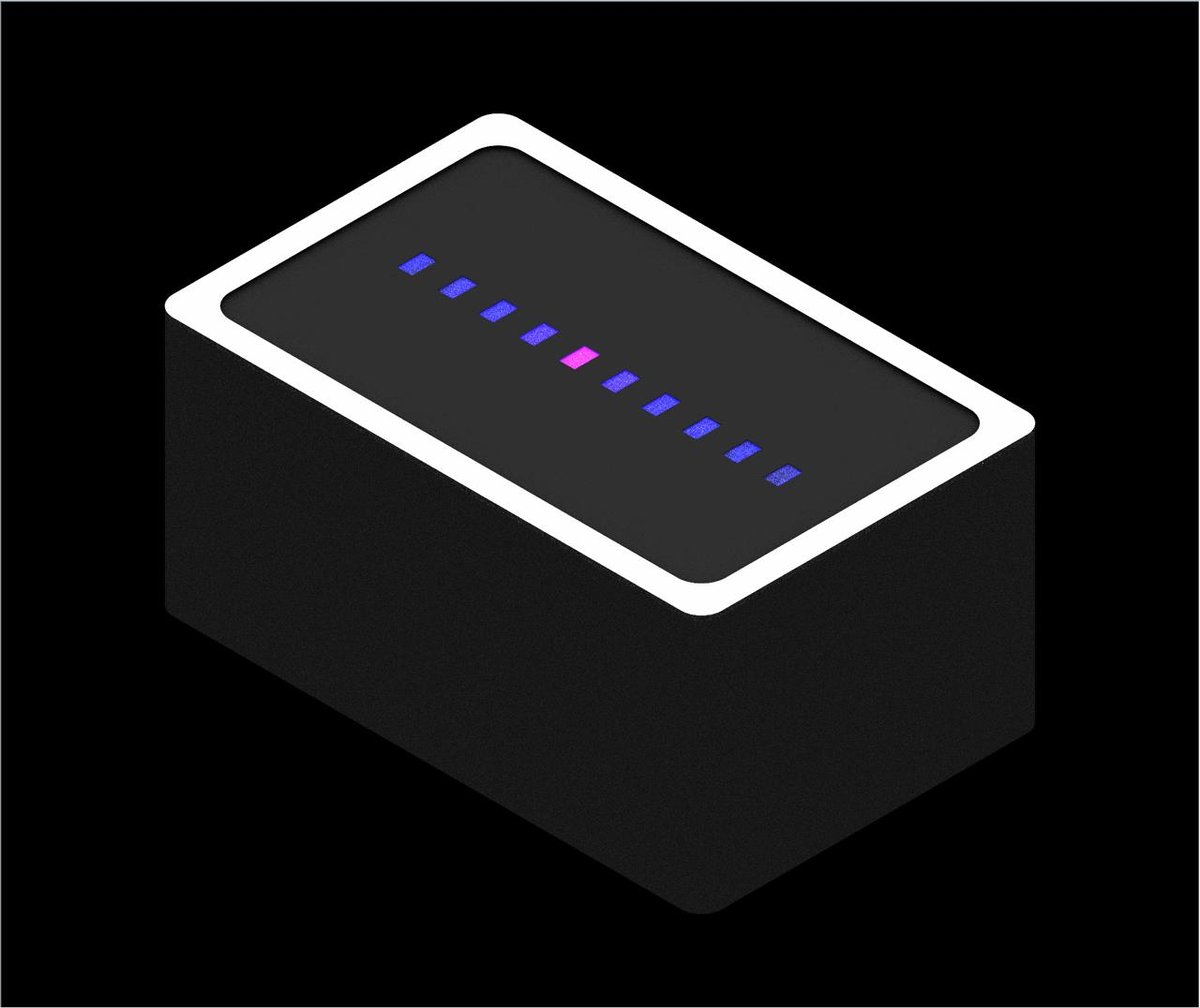
For each channel, record the LED source condition, panel luminance, coupled flux, and relevant tolerance case. Then calculate the array's matching ratio from those values. For different colors, preserve the source spectra and photometric treatment used in the requirement. If drive-current changes are evaluated, check the electrical and thermal limits outside the optical model as part of the design review.
The emitting-face geometry can alter both apparent fill and viewing-angle behavior. Compare polished, textured, diffusing, or lensed faces only with optical properties supported by measurement or a documented supplier model. TracePro Expert includes RepTile for procedural modeling of repeated microstructures. Use it when the surface is defined by a deterministic repeated structure. Do not substitute a named mold finish or roughness value for a characterized scatter property.
Use a test matrix, not one favorable trace
A nominal trace cannot establish production margin. At minimum, the comparison matrix should include the specified LED output range, die position tolerance, LED-to-pipe gap, lateral placement, pipe position, and the viewing positions required by the product. Add material and surface-property ranges only when there is evidence for them.
For each case, keep a short output set:
- Luminance map for the driven channel and neighboring off channels
- Matching ratio across channels intended to appear equal
- Crosstalk ratio from the driven channel to each relevant neighbor
- Flux Report values used for the coupling and loss comparison
- Incident Ray Table or Path Sorting Table evidence for the dominant leakage path
A real TracePro model image and at least one quantitative output example must be added before publication. Until those exist, this article describes a defensible workflow but does not demonstrate a measured result. The model should then be correlated against a prototype using the same drive condition, viewing geometry, and channel definitions.
Keep the optical model connected to the mechanical design
TracePro can import supported native CAD and exchange formats, including STEP, IGES, and SAT, subject to the available translators. Imported geometry becomes part of the TracePro optical model. It is not a live native CAD model.
For a connected SOLIDWORKS workflow, RayViz can assign optical properties and sources, trace rays in the CAD assembly, and save a TracePro model with those definitions. If the SOLIDWORKS assembly changes, TracePro provides an Update from RayViz workflow. Use the updated geometry to rerun the same tolerance and viewing matrix rather than comparing results from different test definitions.
Make the design decision before tooling
The useful outputs are not a convincing ray picture or a single bright channel. They are the panel luminance under specified conditions, the matching ratio across the array, the off-to-on crosstalk ratio for each neighbor, and the evidence that identifies the dominant path.
A non-sequential ray-tracing model can test those quantities while the LED position, pipe entrance, clear runner, PCB finish, panel material, and opaque barriers are still changeable. TracePro's luminance maps, Flux Reports, Incident Ray Tables, and Path Sorting Tables support the workflow without inventing universal thresholds. Explore TracePro illumination analysis, or request a free TracePro trial to evaluate an indicator assembly before the mold is cut.